// TODO: write this post
Category: Projects
TL;DR:
This is an attempt at reverse-engineering the DJI Ronin SC camera gimbal with the following goals:
- using the DJI focus motor separately from the gimbal,
- controlling the gimbal using custom software,
- using the gimbal on a jib/crane-like setup,
- fixing the (many) annoyances and limitations of the official DJI app.
This blog post serves both as my personal notepad and as a starting point for anyone else going down the same path in the future (perhaps with a different DJI device). As the work is still in progress, the post will be updated occasionally.
Part 1: Physical connections
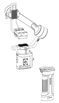
Since this is a rather expensive gadget, I’d like to avoid taking it apart as much as possible. Thankfully, the FCC publishes independent test reports of all RF-emitting gadgets sold in the US, including photos of the wiring and PCBs: https://fccid.io/2ANDR-R181902. Since many of the same accessories fit the Ronin S as well, its FCC report is also quite useful: https://fccid.io/2ANDR-RS11804. If you see photos of components on a blue mat in this article, I’ve likely clipped them from these.
Battery grip mount
The gimbal is split into two main parts – the battery grip and the gimbal head+control unit. Connecting the two is a set of 6 flat contacts on the grip with corresponding pogo pins on the head unit. Presumably, these carry only power, but I have not bothered confirming this.
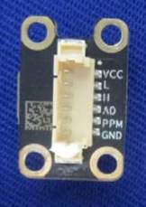
Side connectors
The gimbal has two sets of side accessory connectors, this time with 8 flat pads on the head and corresponding pogo pins on the accessories. Detaching them from the body by removing the 4 hex screws holding them in place reveals a conveniently labeled PCB and rather annoyingly tiny internal header.
A few minutes of poking with the smallest multimeter probe I could find reveals the following correspondence:
//TODO: include pinout
This whole project started several months ago, when I discovered the most amazing thing: 5m of RGB LEDs can be had for less than 5€ on AliExpress!
The idea was simple: my phone has a notification LED that blinks with different colors to signal that there are unread notifications, but since my phone is usually on my desk in a flip case (and probably under a stack of paper), I don’t usually see it. So how neat would it be, if my entire room mirrored that LED so I never missed a notification again?
If you don’t care about the LEDs and control circuits themselves and just want to know how I achieved notification LED mirroring, skip to this section.
The LEDs
The RGB(W) strip I chose is the RGBWW 5050 model. The WW part stands for Warm White, meaning the actual RGB LEDs alternate with warm white LEDs and the 5050 refers to the RGB LED model, which is the stronger of the two most common ones (the other being 3528).
I opted for RGBW instead of standard RBG as I wanted to be able to flash a notification color while still illuminating my room enough to work. The warm white (as opposed to a more standard, cooler white) is just a personal preference.
The driver circuit
The control server
I was initially planning on using my home NAS server to control the LEDs with just a long USB extension cable running to them, but looking at the pile of ESP8266s on my desk gave me a better idea: use esp-link to expose the driver board’s serial port over the network and control it directly.
As the ESP8266 requires a 3,3V supply, I had to step down some of the existing 5V even further. Luckily, I had some step-down boards handy and just jerry-rigged them onto the main board with some wires.
I loaded the ESP8266 with esp-link, which involved first updating its bootloader and then flashing the esp-link binary onto the chip. The configuration was also rather simple and involved connecting to an open Wi-Fi hotspot, created by the chip and entering the credentials to my home Wi-Fi, after which the ESP switched to station mode and acted just like any other device on my network.
I proceeded to connect the TX, RX and RST pins of my MCU to the ESP according to the official instructions, which gave me access to its serial port from any device on the network, as well as allowed me to remotely flash the MCU’s firmware at any time.
The firmware
The original firmware consisted of some 200 lines of C that were about as fast and fexible as an 80-year-old with osteoporosis. You can see it [here], but I don’t advise you to.
The firmware that I use now is actually not terrible and is available on GitLab [here]. You’re free to use it if you want to – it’s all GPLv2.
Because I can’t be bothered with proper documentation, here’s a short snippet that shows off the functionality (> is the prompt)
> asdf
E Invalid command!
> P ("print" the current state of the LEDs)
PR255G0B0W150
> SB150W0 ("set" specified channels to new values)
PR255G0B150W0
> FR0G0B0W0 ("fade" specified channels to new values
PR0G0B0
The firmware allows you to define (at compile time) any number of channels, each with a channel name (a single character) and its corresponding PWM output pin. You can see some examples in the README.
The notification mirroring
Ok, now for the interesting part. The never-before-seen part. The only part that hasn’t been posted all over Instructables 100s of times. How can I monitor the state of my phone’s notification LED and send that information to the light server?
Not all that surprisingly, there isn’t a simple function in the Android SDK that would allow me to just do that. So, I had to get creative and dig deeper into the system itself.
Looking through the sources of the particular ROM I was using (based on LineageOS, although the same applies for stock Android, too), [………..]
Once I know what function I am interested in, I need a way to tap into it and mess with its execution. Fortunately, that is exactly what the XPosed Framework was designed to do. After taking care of all the boilerplate required for XPosed to load my module into the right binary (which can be found here), I was able to tap the […] function like so:
public class Main implements IXposedHookLoadPackage {
    private static final String NMS_CLASS = "com.android.server.notification.NotificationManagerService";
    @Override public void handleLoadPackage(XC_LoadPackage.LoadPackageParam lpparam) throws Throwable {
        if (lpparam.packageName.equals("android") && lpparam.processName.equals("android")) {
            XposedBridge.log("Hooked android");
            XposedHelpers.findAndHookMethod(NMS_CLASS, lpparam.classLoader, "updateLightsLocked", methodHook);
        }
    }
}
This allows me to execute my code every time that function is called, just before it starts executing, giving me full control over the parameters it receives. Using a possibly one of the ugliest parts of Java – reflection, I was finally, after hours of staring at Android source code and dumping strange variables to logcat (because setting up an OS-level debugger is simply too much hassle), able to understand what all the variables meant and how they related to the LED’s action and came up with this beautiful mess of spaghetti code:
static XC_MethodHook methodHook = new XC_MethodHook() {
    @Override
    protected void afterHookedMethod(final MethodHookParam param) throws Throwable {
        // type: NotificationManagerService
        Object nms = param.thisObject;

        Field mNotificationLightField = NotificationManagerService.getDeclaredField("mNotificationLight");
        mNotificationLightField.setAccessible(true);

        // type: Light
        Object mNotificationLight = mNotificationLightField.get(nms);

        Class Light = mNotificationLight.getClass()

        Field mColorField = Light.getDeclaredField("mColor");
        mColorField.setAccessible(true);
        int mColor = mColorField.getInt(mNotificationLight);

        Field mFlashingField = Light.getDeclaredField("mFlashing");
        mFlashingField.setAccessible(true);
        boolean mFlashing = mFlashingField.getBoolean(mNotificationLight);

        XposedBridge.log("Light color: " + mColor);
        XposedBridge.log("Light flashing: " + mFlashing);
    }
};
Tying it all together
With all the pieces working, it was time to connect everything together. For every light event, after the above code decoded it, the details of the event (ON/OFF, color, blinking speed) would be send to the light server in the form of a special command. The server would forward it to the MCU, where the firmware would read the details and save them into its memory.
With the LED state information now synchronized to the controller, it was simply a matter of writing a fade function to mimic the one used by my phone and the project was done.
We’ve all been there. You’re all set for your big presentation: beautiful template, just the right amount of text, fancy graphics and that one perfectly timed star wipe for comedic effect. You’re just about to leave when you remember, that the world isn’t an Apple commercial. You pack the HDMI-VGA adapter and a second one for backup, your brand new absurdly expensive slide clicker, you make sure your presentations looks good on a 4:3 screen too and walk into the hall with the confidence of a Python developer, only to be greeted by a hard-wired Windows XP computer with Office 2007…
I won’t bother you with any more stories. Here’s what I want: I want to be able to walk around with a tablet in my hand, the presenter notes on it and generally run whatever I want on it without having to worry about compatibility ever again. Why? Mostly because it looks futuristic and cool.
Possible easy solutions
Let’s get some of the obvious solutions out of the way first:
- Office365 PowerPoint broadcast: low quality, requires a good Internet connection on both sides, works only in PowerPoint
- Windows 10 “Stream to this PC”: only works on Windows 10, requires a (compatible) Wi-Fi card in the target PC
- Miracast/Chromecast/WhateverCast: rarely available, even if I had my own dongle it would still require messing with the projector
Requirements
If you want to use this setup, here’s what you’ll need:
- A rooted Android smartphone (that supports USB tethering)
- A Windows (7 or above) laptop (a touch 2-in-1 is even better)
- A USB cable for your phone
The virtual display
The trickiest part of this setup is the virtual display. I don’t want to stream my laptop’s display, because I want to have my presenter view on it. I want Windows to think there’s an actual extra physical monitor connected to it. This is something that is very hard to achieve, but luckily, some Windows driver magicians over at datronicsoft have already done that and packaged into a rather neat application called spacedesk.
After installing the spacedesk driver on the laptop, I can connect to it from any device on the network using one of several available viewers: Windows, Android, iOS and HTML5. I’m interested in the HTML5 one because it is as cross-platform as anything can possibly be.
The viewer
Spacedesk’s HTML5 viewer is normally available on their website, but for several reasons, I want to serve the files to the target computer myself. A quick CTRL+S gets me the page and all of its JS into a folder that I can serve with a simple web server on my phone.
Out-of-the-box, the viewer doesn’t support Mozilla Firefox for “performance reasons”, but in my testing, it works just fine and I still prefer a slow connection to no connection at all, so a simple search-and-replace on the source code gets rid of the browser checks:
sed -i 's/browser.name === "Firefox"/\0 \&\& false/' spacedesk.min.jsSome further modification was done to pre-populate the address field with the (static) address of the phone’s tethering interface.
A simple httpd from Busybox will suffice to serve the files from the phone and present them to the target computer.
The network
// TODO
The proxy
// TODO